ShopDreamUp AI ArtDreamUp
Deviation Actions


Suggested Deviants


![MAKS Multipurpose Aerospace System ortho [1] [new]](https://images-wixmp-ed30a86b8c4ca887773594c2.wixmp.com/f/e0dc8eb0-7eb3-4716-b7a1-4364a45acdc0/d7qh57x-abbc03c5-45f8-4d42-869c-a4efdafce108.jpg/v1/crop/w_184,h_184,x_28,y_0,scl_0.0736,q_70,strp/maks_multipurpose_aerospace_system_ortho__1___new__by_unusualsuspex_d7qh57x-92s-2x.jpg?token=eyJ0eXAiOiJKV1QiLCJhbGciOiJIUzI1NiJ9.eyJzdWIiOiJ1cm46YXBwOjdlMGQxODg5ODIyNjQzNzNhNWYwZDQxNWVhMGQyNmUwIiwiaXNzIjoidXJuOmFwcDo3ZTBkMTg4OTgyMjY0MzczYTVmMGQ0MTVlYTBkMjZlMCIsIm9iaiI6W1t7ImhlaWdodCI6Ijw9MjUwMCIsInBhdGgiOiJcL2ZcL2UwZGM4ZWIwLTdlYjMtNDcxNi1iN2ExLTQzNjRhNDVhY2RjMFwvZDdxaDU3eC1hYmJjMDNjNS00NWY4LTRkNDItODY5Yy1hNGVmZGFmY2UxMDguanBnIiwid2lkdGgiOiI8PTQwMDAifV1dLCJhdWQiOlsidXJuOnNlcnZpY2U6aW1hZ2Uub3BlcmF0aW9ucyJdfQ.8sRGGtJgA53NVB0e3t6DTjuudJN4tjZbs5461YuAzyg)
![MAKS Multipurpose Aerospace System ortho [1] [new]](https://images-wixmp-ed30a86b8c4ca887773594c2.wixmp.com/f/e0dc8eb0-7eb3-4716-b7a1-4364a45acdc0/d7qh57x-abbc03c5-45f8-4d42-869c-a4efdafce108.jpg/v1/crop/w_92,h_92,x_14,y_0,scl_0.0368,q_70,strp/maks_multipurpose_aerospace_system_ortho__1___new__by_unusualsuspex_d7qh57x-92s.jpg?token=eyJ0eXAiOiJKV1QiLCJhbGciOiJIUzI1NiJ9.eyJzdWIiOiJ1cm46YXBwOjdlMGQxODg5ODIyNjQzNzNhNWYwZDQxNWVhMGQyNmUwIiwiaXNzIjoidXJuOmFwcDo3ZTBkMTg4OTgyMjY0MzczYTVmMGQ0MTVlYTBkMjZlMCIsIm9iaiI6W1t7ImhlaWdodCI6Ijw9MjUwMCIsInBhdGgiOiJcL2ZcL2UwZGM4ZWIwLTdlYjMtNDcxNi1iN2ExLTQzNjRhNDVhY2RjMFwvZDdxaDU3eC1hYmJjMDNjNS00NWY4LTRkNDItODY5Yy1hNGVmZGFmY2UxMDguanBnIiwid2lkdGgiOiI8PTQwMDAifV1dLCJhdWQiOlsidXJuOnNlcnZpY2U6aW1hZ2Uub3BlcmF0aW9ucyJdfQ.8sRGGtJgA53NVB0e3t6DTjuudJN4tjZbs5461YuAzyg)


![Saturn V Launch Escape System Tech Readout [new]](https://images-wixmp-ed30a86b8c4ca887773594c2.wixmp.com/f/e0dc8eb0-7eb3-4716-b7a1-4364a45acdc0/d7s2hig-b7f0c358-e0cb-40e0-ae24-636f9f8136d7.jpg/v1/crop/w_184,h_184,x_28,y_0,scl_0.0736,q_70,strp/saturn_v_launch_escape_system_tech_readout__new__by_unusualsuspex_d7s2hig-92s-2x.jpg?token=eyJ0eXAiOiJKV1QiLCJhbGciOiJIUzI1NiJ9.eyJzdWIiOiJ1cm46YXBwOjdlMGQxODg5ODIyNjQzNzNhNWYwZDQxNWVhMGQyNmUwIiwiaXNzIjoidXJuOmFwcDo3ZTBkMTg4OTgyMjY0MzczYTVmMGQ0MTVlYTBkMjZlMCIsIm9iaiI6W1t7ImhlaWdodCI6Ijw9MjUwMCIsInBhdGgiOiJcL2ZcL2UwZGM4ZWIwLTdlYjMtNDcxNi1iN2ExLTQzNjRhNDVhY2RjMFwvZDdzMmhpZy1iN2YwYzM1OC1lMGNiLTQwZTAtYWUyNC02MzZmOWY4MTM2ZDcuanBnIiwid2lkdGgiOiI8PTQwMDAifV1dLCJhdWQiOlsidXJuOnNlcnZpY2U6aW1hZ2Uub3BlcmF0aW9ucyJdfQ.5oNHvZf7fn-kJiUz73RebEKCtlQFwpawUXUG1MToAZY)
![Saturn V Launch Escape System Tech Readout [new]](https://images-wixmp-ed30a86b8c4ca887773594c2.wixmp.com/f/e0dc8eb0-7eb3-4716-b7a1-4364a45acdc0/d7s2hig-b7f0c358-e0cb-40e0-ae24-636f9f8136d7.jpg/v1/crop/w_92,h_92,x_14,y_0,scl_0.0368,q_70,strp/saturn_v_launch_escape_system_tech_readout__new__by_unusualsuspex_d7s2hig-92s.jpg?token=eyJ0eXAiOiJKV1QiLCJhbGciOiJIUzI1NiJ9.eyJzdWIiOiJ1cm46YXBwOjdlMGQxODg5ODIyNjQzNzNhNWYwZDQxNWVhMGQyNmUwIiwiaXNzIjoidXJuOmFwcDo3ZTBkMTg4OTgyMjY0MzczYTVmMGQ0MTVlYTBkMjZlMCIsIm9iaiI6W1t7ImhlaWdodCI6Ijw9MjUwMCIsInBhdGgiOiJcL2ZcL2UwZGM4ZWIwLTdlYjMtNDcxNi1iN2ExLTQzNjRhNDVhY2RjMFwvZDdzMmhpZy1iN2YwYzM1OC1lMGNiLTQwZTAtYWUyNC02MzZmOWY4MTM2ZDcuanBnIiwid2lkdGgiOiI8PTQwMDAifV1dLCJhdWQiOlsidXJuOnNlcnZpY2U6aW1hZ2Uub3BlcmF0aW9ucyJdfQ.5oNHvZf7fn-kJiUz73RebEKCtlQFwpawUXUG1MToAZY)


Suggested Collections


You Might Like…


Featured in Groups


Description
Open Cycle Gas Core Rocket and Propulsion Bus
Design based on NASA TM X-2772 Reactor Moderator, Pressure Vessel, And Heat Rejection System of An Open-Cycle Gas-Core Nuclear Rocket Concept Link to PDF.
The study describes a preliminary design of a 6000 megawatt open-cycle gas-core nuclear thermal rocket engine purposed to provide for very fast round trip interplanetary missions.
NASA TM X-67823 Gas Core Rocket Reactors-A New Look Link to PDF describes fast manned Mars missions (called currier missions) with durations of 80, 100, 150, and 2OO days. Jupiter and Saturn missions are also considered.
Introduction
I set out to simply model an open-cycle gas core rocket, everything starts out simple. However, one does not, simply, model an open cycle gas core nuclear thermal rocket.
A number of talented individuals added their expertise to this project, joining in on my G+ discussion threads, you will find them quoted in the text below and credited at the bottom of the page.
Of note, Dogmatic Pyrrhonist, talented creator of KSP mods, lent his design insight. Dogmatic Pyrrhonist’s eye for realism in engine detailing is impeccable, and I’ve learned a great deal from his design thought as we shared results in the process of modeling our respective engines.
The Open Cycle Gas Core Rocket
Like the solid-core nuclear rocket engine, the job of a gas-core engine is to heat hydrogen and then expand it through a nozzle to convert the thermal energy into thrust. In order to obtain a higher specific impulse than the 825 seconds of the solid core, a gas core has to produce hotter hydrogen. For a specific impulse of 825 seconds, the hydrogen temperature at the nozzle inlet is approximately 2500 K. A temperature of 22,000 K is required for a specific impulse of 5OOO seconds. The temperature levels required for specific impulses in the range 3000 t o 5OOO seconds cannot be obtained by simply running solid-core type fuel elements at a higher temperature because the uranium, must be hotter than the hydrogen, and at these elevated temperatures the fuel elements would simply melt and vaporize.
The gas-core concept is to use an incandescent, radiating ball of fissioning uranium plasma as the "fuel element." The nuclear heat released within the uranium plasma leaves its surface in the form of thermal radiation, or photons. This thermal energy is picked up by a surrounding stream of hydrogen propellant, which is then expanded through a nozzle to produce thrust.
Description and Specifications
The reactor is spherical: a titanium pressure shell with an internal 4.267-meter (14-ft) cavity surrounded by a 0.61-meter (2-ft) thick Beryllium oxide (BeO) reflector-moderator. The reactor is fueled with enriched uranium (98 percent U235) and generates about 6000 megawatts of thermal energy, with a hydrogen propellant flow rate of 4. 54 kilograms per second (10 Ib/sec).
Engine thrust: 196,600 newtons (44, 200 Lbs). Specific impulse: 4400 seconds.
The study notes these data are consistent with a mission analysis of a very fast 80-day manned Mars round trip (Mars courier mission) with an engine having a total weight of about 100,000 kilograms.
The edge or radiating temperature of the plasma is about 26,000 K (47,000 R). The hydrogen propellant is seeded with about 10 percent by weight of small particles (about the size of smoke particles) which absorb the thermal radiation from the plasma and then convectively heat the hydrogen. The seeded hydrogen enters the cavity through porous or slotted walls.
The study suggests seeding material of either graphite or tungsten.
Winchell Chung
Hydrogen, unfortunately is transparent to gamma radiation. Hence the seeding.
As example, Winchell describes the properties of the seeding material, per use in a Nuclear Lightbulb engine.
In the nuclear lightbulb: The tungsten dust that the propellant is seeded with has a particle diameter of 0.05 microns. The seed density is 1.32 x 10^-2 lb/ft^3, which is about 3.9 percent of the inlet propellant density. This can probably be reduced if tungsten dust was in the form of thin flat plates instead of spherical particles.
Physicist Luke Campbell
Graphite and tungsten are the two things that stay solid at higher temperatures than anything else. Seeding [the propellant] gives you a reasonable amount of black-body radiation, whereas the gas would be optically thin and not thermally radiate much. Then you could couple the heat from the reactor to the propellant via radiation.
Nuclear Fuel
As Winchell Chung observes, only in rare cases (like chemical propulsion) are propellant and fuel the same thing.
For the gas core rocket, the fuel is enriched uranium (98 percent U235 ) and hydrogen is the propellant. For a typical Mars mission the gas core rocket needs 3,350 kg of enriched 98 percent U235 .
Because it is enriched uranium criticality is a concern.
Dean Calahan
[The uranium] embedded in a waxy substance. For example wax, or LDPE. The wire-rod form could just be plastic-coated. The powder form could just be evenly distributed particles in bulk plastic.
To access it for propulsion, you simply easily melt away the plastic.
Luke Campbell
Plastic and wax would act to moderate the neutrons, increasing your criticality problems. You might get around this by heavily loading the wax/plastic with boron or lithium or gadolinium, which are good at absorbing thermal neutrons.
Reactor Operation
Reactor startup would be achieved by first establishing the hydrogen flow. Next uranium particles would be blown into the dead cavity region to achieve nuclear criticality. The power would then be increased to a level sufficient to vaporize the incoming uranium rod.
A possible fuel injection technique consists of pushing a very thin rod of solid uranium metal through a shielded pipe (perhaps made of cadmium oxide) that penetrates the moderator. As it enters the cavity, the uranium vaporizes and rises in temperature to about 55,000 K.
Criticality is maintained by adding uranium and increasing the hydrogen pressure till full power is achieved. Thereafter, only enough uranium is added to the plasma to make up for the fuel loss to the propellant. Based on flow experiments the uranium loss rate is expected to be of the order of l/100th of the hydrogen propellant flow rate. The reactor can be shut down by simply turning off the uranium fuel supply.
Radiative Cooling versus Regenerative Cooling
For the initial research an upper limit of 3000 seconds on specific impulse resulted from the use of only regenerative cooling to remove heat deposited in various parts of the engine structure. Higher specific impulses would require a space radiator.
Seven percent of reactor power is expected to be deposited into the reflector-moderator (as 420 megawatts of waste heat) by the attenuation of high-energy gamma and neutron radiation. The waste heat is rejected to space by an external high pressure helium gas, fin and tube type, radiator.
NASA TM X-2772 suggested rectangular radiator panels arrayed around the rocket nozzle and, what immediately struck me about this configuration, is the that radiator panels in this arrangement would reflect radiation foreword, irradiating vehicle and crew. So, a long truss was needed to carry much longer, radiator panels of a truncated triangular form, positioned forward of the engine – the truncated triangular panel conforms to the safe conical radiation shadow cast by a shadow shield.
This called for a 54.5 meter (178.9 ft) truss between gas core reactor and propellant tank to carry four radiator panels, in cruciform configuration.
Radiator panels are 51.4 meters (168.9 ft) long, with a forward elevation (above and below the truss) of 29.9 meters (98.1 ft) and an aft elevation of 3 meters (9.8 ft).
Radiation Shadow Shield
Luke Campbell
Note that fission neutrons and gammas will scatter off of anything they can reach, turning each unshielded strut and pipe and surface into another radiation source. The shadow shield will need to intercept all these scattered neutrons and gammas as well as those directly streaming from the reactor – you probably want it so that anything on the shielded side can't see anything on the unshielded side without going through the shadow shield.
Struts can pierce the shield if they zig-zag. That way, radiation can't take a straight path through – it might follow a strut part way, but then plow into the borated poly when the strut turns.
Winchell Chung
Shared NASA TM X-67927 Crew Radiation Dose From The Plume of A High Impulse Gas-Core Nuclear Rocket During A Mars Mission Link to PDF
The study is focused on that part of the total radiation problem that arises from the fission fragments in the gas core rocket plume volume, examining crew dose in two locations (100 and 200 meters from the plume source) for specific missions. The missions chosen are manned "courier" round-trip missions with durations of 80, 100, 150, and 2OO days. These fast trip times require a large number of megawatt hours of energy, and crew radiation dose is a function of the energy required for a mission.
As it turns out, I needed that length of truss.
Atomic Rockets Link Crew radiation dose from plume of Gas-Core rocket
In the open-cycle gas-core nuclear rocket concept the heat source is fissioning uranium gas. This released heat is radiated to and absorbed by the hydrogen propellant. The heated propellant is exhausted through a nozzle, producing thrust. The fission fragments that are formed and the unfissioned uranium fuel are also exhausted into the vacuum of space. As the plume is formed, the crew is exposed to gamma radiation from the fission fragments in the plume.
The radiation dose to the crew from the fission fragments in the plume can be separated into two components. Component one results from the fact that there is a microscopic amount of plume material that has sufficient kinetic energy to flow back towards the vehicle. Some of this material will strike and stick to the vehicle. Since this material will contain fission fragments, these gamma radiation sources will stay with the crew throughout the entire trip and this dose could represent a significant source of radiation. Masser(3) has estimated this dose and has concluded it would be less than 10-3 rem for a typical manned Mars mission.
Component two of the dose results from the fission fragment distribution throughout the entire plume volume and is potentially much larger than component one. Since the plume contains over 99 percent of the exhausted material, 99 percent of the fission fragments will be in the plume. It is the purpose of this paper to estimate the radiation dose rate and total dose to the crew from the fission fragments in the plume for four specific missions to the planet Mars.
Another source of radiation is caused by the delayed decay of the fission fragments that are passing through the nozzle. This includes delayed neutrons which can cause secondary fissioning and gamma's. This source, however, has not been included. There is another radiation source associated with the gas-core reactor, that of the reactor core. This radiation source, along with solar radiation, must be ultimately considered when total dose rates to the crew are evaluated. This study, however, is concerned only with that part of the total radiation problem that arises from the fission fragments in the plume volume.
For the most probable fission fragment retention, time of 100 seconds, and crew nozzle separation of 100 meters, the radiation dose varied from 170. to 36. rem for the 80 and 200 day round trip times respectively. Five centimeters of lead shielding would reduce the radiation dose by two orders of magnitude, thereby protecting the crew. The increase in vehicle weight would be insignificant. For example, a shield of five centimeters thickness and four meters in diameter would add 7120 kilograms to the vehicle gross weight of 0.94 million kilograms. Also additional attenuation is available In the form of liquid hydrogen propellant, spacecraft structure, nuclear fuel, equipment, and stores.
Luke Campbell
Lead would be good for shielding against the prompt fission gamma rays and the gamma rays from the radioactive decay of the fission products and actinides. It would be a poor choice for protecting against neutron radiation. For that, you will want several (or several tens) of cm of iron to slow down fast neutrons to less than an MeV via inelastic collisions with the nuclei (these are collisions that leave the nucleus in an excited state, whose energy comes from the kinetic energy of the neutron), then another several tens of centimeters of borated polyethylene to slow down and absorb the slower neutrons. Make sure to put the lead shield behind the neutron shield, so the neutrons encounter the iron and borated poly first (neutron reactions can also generate gamma rays, but not so much the other way around).
Running a few numbers, over the energy range typical of reactor neutrons, it will always be more mass effective to skip the iron part of the shield and just add more polyethylene. For the prompt fission neutrons you will be looking at something like a 1/e interaction length of about 10 cm. Each interaction will scatter the neutron and on average its energy will drop by half. The interaction length decreases with each scatter until you get to a broad plateau of a 1 cm scattering length for energies less than 100 keV - this will take about 3 to 4 scatters on average to reach from fission spectrum neutrons. Then you are looking at another seven scatters or so until the energy drops low enough that it will be sopped up by the boron. Since the interaction length keeps decreasing, and because it is a random walk type process (with the neutron going backwards as well as forwards), you can probably assume that any neutron will be absorbed within about 10 cm of where it first scatters. So if you want to decrease the neutron flux by a factor of 10,000, you will need a thickness of [ln(10,000) + 1] * 10 cm ~= 100 cm of borated polyethylene.
On Luke Campbell’s recommendation I elected to go with 5% borated polyethylene rather than the layered lead and polyethylene, and increased the shadow shield diameter from the report recommendation of a 4.26 meters (14 ft) diameter shield to a 100cm (3 ft) thick by 6.7 05 meter (22 ft) diameter shadow shield.
Data for 5% Borated Polyethylene Neutron Radiation Shielding, scroll down at the link, DEQ Tech
Hydrogen Atom Density/cm^3: 7.5 x 10^22
Natural Isotope Distribution: 99.98% 1H
Boron Atom Density/cm^3: 3.0 x 10^21
Total Density: 1.08 g/cm^3 (67 lb/ft^3)
Radiation Properties:
Macroscopic Thermal Neutron Cross Section: 2.00 (cm^-1)
Gamma Resistance: 5 x 10^8 rad
Neutron Resistance: 2.5 x 10^17 n/cm^2
Radiation Simulations
As noted above Dogmatic Pyrrhonist and I had been working out the design of our gas core rockets and sharing the results. On one of Dogmatic Pyrrhonist’s threads Ron Fischer offered the following insight:
Ron Fischer
You can use lighting and shadows in your CG rendering program to analyze your shadow shield, this is where the original math for lighting simulation came from: radiation studies on tanks in the 60s. This is (oddly enough) where computer graphics lighting began. I cannot find an exact reference but believe it was Lawrence Livermore Labs. Might as well go "Back to the Future" on that one!
I found this to be a compelling proposition, an opportunity to test out the validity of one’s design.
Dogmatic Pyrrhonist and I both set about individually setting up a radiation simulation by CG lighting; his results are to be found at links in this thread November 6, 2015
For more detail and my results see Radiation Design by CG Modeling.
Integrated Elements of The Open Cycle Gas Core Rocket
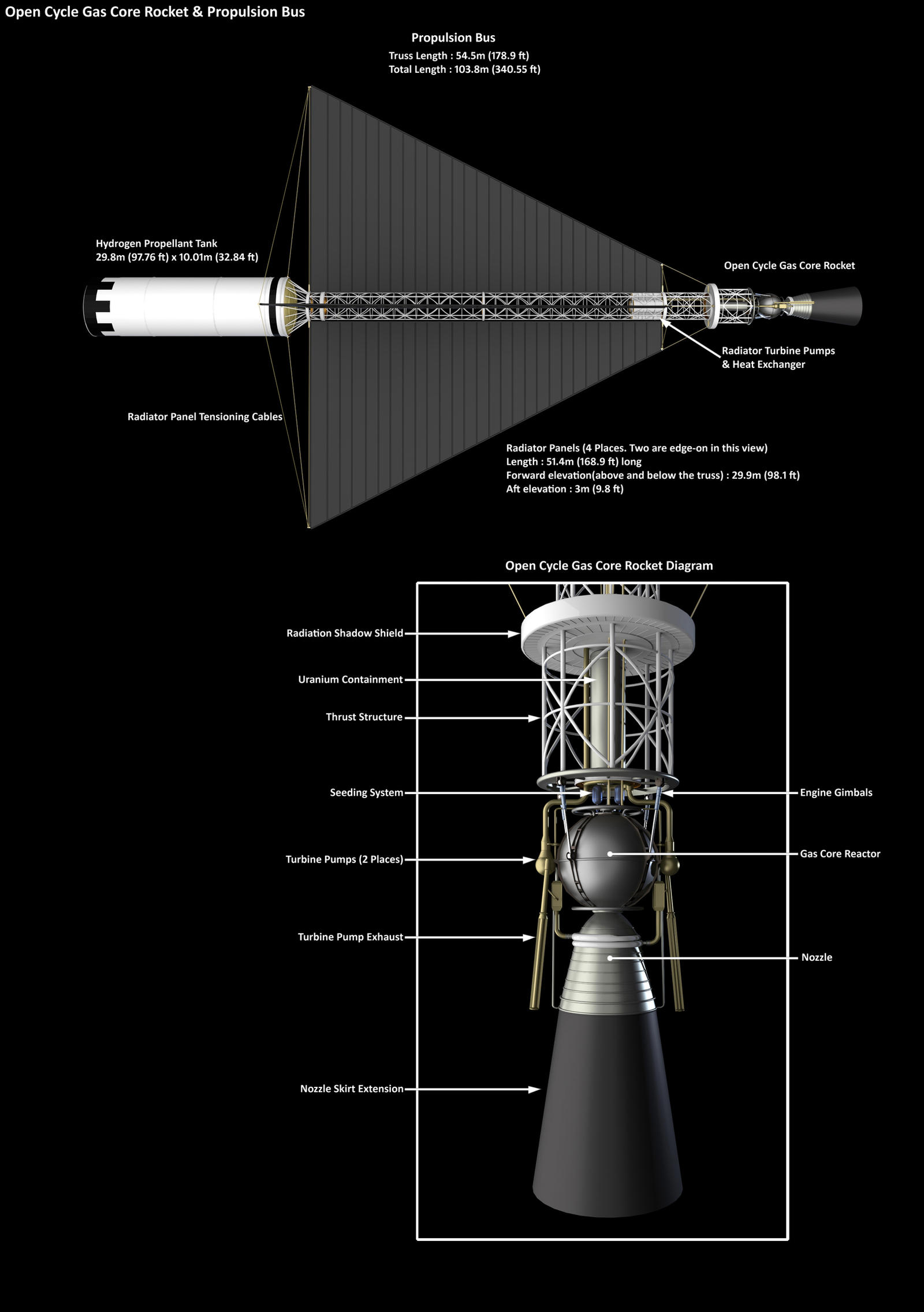
So, rather than a simple gas core rocket diagram, we have the integrated elements of the radiatively cooled gas core rocket, the gas core reactor, shadow shield, and entire propulsion bus, the radiator panels, and a hydrogen propellant tank (one of four) scaled for the proposed 80-day Mars courier mission.
Related Art
The R.A. Heinlein
Open-Cycle Gas-Core Nuclear Thermal Rocket
Mars Courier Mission, Earth-Orbit Escape Burn With Radiator SFX
Mars Courier Mission, Earth-Orbit Escape Burn
Mars Courier Mission, Earth-Escape Tank Jettison
Radiation Design by CG Modeling
Gas Core Rocket New Radiation Simulation
Acknowledgements
A number of talented and knowledgeable individuals joined in on my G+ discussion threads lending their expertise to this project. I would like to express my thanks and appreciation to the following individuals for their contributions:
Winchell Chung of Atomic Rockets
Luke Cambell, Physicist
Dean Callahan, Smithsonian Institution
Dogmatic Pyrrhonist, talented creator of KSP mods
Ron Fischer, Virtual Production Engineer
Design based on NASA TM X-2772 Reactor Moderator, Pressure Vessel, And Heat Rejection System of An Open-Cycle Gas-Core Nuclear Rocket Concept Link to PDF.
The study describes a preliminary design of a 6000 megawatt open-cycle gas-core nuclear thermal rocket engine purposed to provide for very fast round trip interplanetary missions.
NASA TM X-67823 Gas Core Rocket Reactors-A New Look Link to PDF describes fast manned Mars missions (called currier missions) with durations of 80, 100, 150, and 2OO days. Jupiter and Saturn missions are also considered.
Introduction
I set out to simply model an open-cycle gas core rocket, everything starts out simple. However, one does not, simply, model an open cycle gas core nuclear thermal rocket.
A number of talented individuals added their expertise to this project, joining in on my G+ discussion threads, you will find them quoted in the text below and credited at the bottom of the page.
Of note, Dogmatic Pyrrhonist, talented creator of KSP mods, lent his design insight. Dogmatic Pyrrhonist’s eye for realism in engine detailing is impeccable, and I’ve learned a great deal from his design thought as we shared results in the process of modeling our respective engines.
The Open Cycle Gas Core Rocket
Like the solid-core nuclear rocket engine, the job of a gas-core engine is to heat hydrogen and then expand it through a nozzle to convert the thermal energy into thrust. In order to obtain a higher specific impulse than the 825 seconds of the solid core, a gas core has to produce hotter hydrogen. For a specific impulse of 825 seconds, the hydrogen temperature at the nozzle inlet is approximately 2500 K. A temperature of 22,000 K is required for a specific impulse of 5OOO seconds. The temperature levels required for specific impulses in the range 3000 t o 5OOO seconds cannot be obtained by simply running solid-core type fuel elements at a higher temperature because the uranium, must be hotter than the hydrogen, and at these elevated temperatures the fuel elements would simply melt and vaporize.
The gas-core concept is to use an incandescent, radiating ball of fissioning uranium plasma as the "fuel element." The nuclear heat released within the uranium plasma leaves its surface in the form of thermal radiation, or photons. This thermal energy is picked up by a surrounding stream of hydrogen propellant, which is then expanded through a nozzle to produce thrust.
Description and Specifications
The reactor is spherical: a titanium pressure shell with an internal 4.267-meter (14-ft) cavity surrounded by a 0.61-meter (2-ft) thick Beryllium oxide (BeO) reflector-moderator. The reactor is fueled with enriched uranium (98 percent U235) and generates about 6000 megawatts of thermal energy, with a hydrogen propellant flow rate of 4. 54 kilograms per second (10 Ib/sec).
Engine thrust: 196,600 newtons (44, 200 Lbs). Specific impulse: 4400 seconds.
The study notes these data are consistent with a mission analysis of a very fast 80-day manned Mars round trip (Mars courier mission) with an engine having a total weight of about 100,000 kilograms.
The edge or radiating temperature of the plasma is about 26,000 K (47,000 R). The hydrogen propellant is seeded with about 10 percent by weight of small particles (about the size of smoke particles) which absorb the thermal radiation from the plasma and then convectively heat the hydrogen. The seeded hydrogen enters the cavity through porous or slotted walls.
The study suggests seeding material of either graphite or tungsten.
Winchell Chung
Hydrogen, unfortunately is transparent to gamma radiation. Hence the seeding.
As example, Winchell describes the properties of the seeding material, per use in a Nuclear Lightbulb engine.
In the nuclear lightbulb: The tungsten dust that the propellant is seeded with has a particle diameter of 0.05 microns. The seed density is 1.32 x 10^-2 lb/ft^3, which is about 3.9 percent of the inlet propellant density. This can probably be reduced if tungsten dust was in the form of thin flat plates instead of spherical particles.
Physicist Luke Campbell
Graphite and tungsten are the two things that stay solid at higher temperatures than anything else. Seeding [the propellant] gives you a reasonable amount of black-body radiation, whereas the gas would be optically thin and not thermally radiate much. Then you could couple the heat from the reactor to the propellant via radiation.
Nuclear Fuel
As Winchell Chung observes, only in rare cases (like chemical propulsion) are propellant and fuel the same thing.
For the gas core rocket, the fuel is enriched uranium (98 percent U235 ) and hydrogen is the propellant. For a typical Mars mission the gas core rocket needs 3,350 kg of enriched 98 percent U235 .
Because it is enriched uranium criticality is a concern.
Dean Calahan
[The uranium] embedded in a waxy substance. For example wax, or LDPE. The wire-rod form could just be plastic-coated. The powder form could just be evenly distributed particles in bulk plastic.
To access it for propulsion, you simply easily melt away the plastic.
Luke Campbell
Plastic and wax would act to moderate the neutrons, increasing your criticality problems. You might get around this by heavily loading the wax/plastic with boron or lithium or gadolinium, which are good at absorbing thermal neutrons.
Reactor Operation
Reactor startup would be achieved by first establishing the hydrogen flow. Next uranium particles would be blown into the dead cavity region to achieve nuclear criticality. The power would then be increased to a level sufficient to vaporize the incoming uranium rod.
A possible fuel injection technique consists of pushing a very thin rod of solid uranium metal through a shielded pipe (perhaps made of cadmium oxide) that penetrates the moderator. As it enters the cavity, the uranium vaporizes and rises in temperature to about 55,000 K.
Criticality is maintained by adding uranium and increasing the hydrogen pressure till full power is achieved. Thereafter, only enough uranium is added to the plasma to make up for the fuel loss to the propellant. Based on flow experiments the uranium loss rate is expected to be of the order of l/100th of the hydrogen propellant flow rate. The reactor can be shut down by simply turning off the uranium fuel supply.
Radiative Cooling versus Regenerative Cooling
For the initial research an upper limit of 3000 seconds on specific impulse resulted from the use of only regenerative cooling to remove heat deposited in various parts of the engine structure. Higher specific impulses would require a space radiator.
Seven percent of reactor power is expected to be deposited into the reflector-moderator (as 420 megawatts of waste heat) by the attenuation of high-energy gamma and neutron radiation. The waste heat is rejected to space by an external high pressure helium gas, fin and tube type, radiator.
NASA TM X-2772 suggested rectangular radiator panels arrayed around the rocket nozzle and, what immediately struck me about this configuration, is the that radiator panels in this arrangement would reflect radiation foreword, irradiating vehicle and crew. So, a long truss was needed to carry much longer, radiator panels of a truncated triangular form, positioned forward of the engine – the truncated triangular panel conforms to the safe conical radiation shadow cast by a shadow shield.
This called for a 54.5 meter (178.9 ft) truss between gas core reactor and propellant tank to carry four radiator panels, in cruciform configuration.
Radiator panels are 51.4 meters (168.9 ft) long, with a forward elevation (above and below the truss) of 29.9 meters (98.1 ft) and an aft elevation of 3 meters (9.8 ft).
Radiation Shadow Shield
Luke Campbell
Note that fission neutrons and gammas will scatter off of anything they can reach, turning each unshielded strut and pipe and surface into another radiation source. The shadow shield will need to intercept all these scattered neutrons and gammas as well as those directly streaming from the reactor – you probably want it so that anything on the shielded side can't see anything on the unshielded side without going through the shadow shield.
Struts can pierce the shield if they zig-zag. That way, radiation can't take a straight path through – it might follow a strut part way, but then plow into the borated poly when the strut turns.
Winchell Chung
Shared NASA TM X-67927 Crew Radiation Dose From The Plume of A High Impulse Gas-Core Nuclear Rocket During A Mars Mission Link to PDF
The study is focused on that part of the total radiation problem that arises from the fission fragments in the gas core rocket plume volume, examining crew dose in two locations (100 and 200 meters from the plume source) for specific missions. The missions chosen are manned "courier" round-trip missions with durations of 80, 100, 150, and 2OO days. These fast trip times require a large number of megawatt hours of energy, and crew radiation dose is a function of the energy required for a mission.
As it turns out, I needed that length of truss.
Atomic Rockets Link Crew radiation dose from plume of Gas-Core rocket
In the open-cycle gas-core nuclear rocket concept the heat source is fissioning uranium gas. This released heat is radiated to and absorbed by the hydrogen propellant. The heated propellant is exhausted through a nozzle, producing thrust. The fission fragments that are formed and the unfissioned uranium fuel are also exhausted into the vacuum of space. As the plume is formed, the crew is exposed to gamma radiation from the fission fragments in the plume.
The radiation dose to the crew from the fission fragments in the plume can be separated into two components. Component one results from the fact that there is a microscopic amount of plume material that has sufficient kinetic energy to flow back towards the vehicle. Some of this material will strike and stick to the vehicle. Since this material will contain fission fragments, these gamma radiation sources will stay with the crew throughout the entire trip and this dose could represent a significant source of radiation. Masser(3) has estimated this dose and has concluded it would be less than 10-3 rem for a typical manned Mars mission.
Component two of the dose results from the fission fragment distribution throughout the entire plume volume and is potentially much larger than component one. Since the plume contains over 99 percent of the exhausted material, 99 percent of the fission fragments will be in the plume. It is the purpose of this paper to estimate the radiation dose rate and total dose to the crew from the fission fragments in the plume for four specific missions to the planet Mars.
Another source of radiation is caused by the delayed decay of the fission fragments that are passing through the nozzle. This includes delayed neutrons which can cause secondary fissioning and gamma's. This source, however, has not been included. There is another radiation source associated with the gas-core reactor, that of the reactor core. This radiation source, along with solar radiation, must be ultimately considered when total dose rates to the crew are evaluated. This study, however, is concerned only with that part of the total radiation problem that arises from the fission fragments in the plume volume.
For the most probable fission fragment retention, time of 100 seconds, and crew nozzle separation of 100 meters, the radiation dose varied from 170. to 36. rem for the 80 and 200 day round trip times respectively. Five centimeters of lead shielding would reduce the radiation dose by two orders of magnitude, thereby protecting the crew. The increase in vehicle weight would be insignificant. For example, a shield of five centimeters thickness and four meters in diameter would add 7120 kilograms to the vehicle gross weight of 0.94 million kilograms. Also additional attenuation is available In the form of liquid hydrogen propellant, spacecraft structure, nuclear fuel, equipment, and stores.
Luke Campbell
Lead would be good for shielding against the prompt fission gamma rays and the gamma rays from the radioactive decay of the fission products and actinides. It would be a poor choice for protecting against neutron radiation. For that, you will want several (or several tens) of cm of iron to slow down fast neutrons to less than an MeV via inelastic collisions with the nuclei (these are collisions that leave the nucleus in an excited state, whose energy comes from the kinetic energy of the neutron), then another several tens of centimeters of borated polyethylene to slow down and absorb the slower neutrons. Make sure to put the lead shield behind the neutron shield, so the neutrons encounter the iron and borated poly first (neutron reactions can also generate gamma rays, but not so much the other way around).
Running a few numbers, over the energy range typical of reactor neutrons, it will always be more mass effective to skip the iron part of the shield and just add more polyethylene. For the prompt fission neutrons you will be looking at something like a 1/e interaction length of about 10 cm. Each interaction will scatter the neutron and on average its energy will drop by half. The interaction length decreases with each scatter until you get to a broad plateau of a 1 cm scattering length for energies less than 100 keV - this will take about 3 to 4 scatters on average to reach from fission spectrum neutrons. Then you are looking at another seven scatters or so until the energy drops low enough that it will be sopped up by the boron. Since the interaction length keeps decreasing, and because it is a random walk type process (with the neutron going backwards as well as forwards), you can probably assume that any neutron will be absorbed within about 10 cm of where it first scatters. So if you want to decrease the neutron flux by a factor of 10,000, you will need a thickness of [ln(10,000) + 1] * 10 cm ~= 100 cm of borated polyethylene.
On Luke Campbell’s recommendation I elected to go with 5% borated polyethylene rather than the layered lead and polyethylene, and increased the shadow shield diameter from the report recommendation of a 4.26 meters (14 ft) diameter shield to a 100cm (3 ft) thick by 6.7 05 meter (22 ft) diameter shadow shield.
Data for 5% Borated Polyethylene Neutron Radiation Shielding, scroll down at the link, DEQ Tech
Hydrogen Atom Density/cm^3: 7.5 x 10^22
Natural Isotope Distribution: 99.98% 1H
Boron Atom Density/cm^3: 3.0 x 10^21
Total Density: 1.08 g/cm^3 (67 lb/ft^3)
Radiation Properties:
Macroscopic Thermal Neutron Cross Section: 2.00 (cm^-1)
Gamma Resistance: 5 x 10^8 rad
Neutron Resistance: 2.5 x 10^17 n/cm^2
Radiation Simulations
As noted above Dogmatic Pyrrhonist and I had been working out the design of our gas core rockets and sharing the results. On one of Dogmatic Pyrrhonist’s threads Ron Fischer offered the following insight:
Ron Fischer
You can use lighting and shadows in your CG rendering program to analyze your shadow shield, this is where the original math for lighting simulation came from: radiation studies on tanks in the 60s. This is (oddly enough) where computer graphics lighting began. I cannot find an exact reference but believe it was Lawrence Livermore Labs. Might as well go "Back to the Future" on that one!
I found this to be a compelling proposition, an opportunity to test out the validity of one’s design.
Dogmatic Pyrrhonist and I both set about individually setting up a radiation simulation by CG lighting; his results are to be found at links in this thread November 6, 2015
For more detail and my results see Radiation Design by CG Modeling.
Integrated Elements of The Open Cycle Gas Core Rocket
So, rather than a simple gas core rocket diagram, we have the integrated elements of the radiatively cooled gas core rocket, the gas core reactor, shadow shield, and entire propulsion bus, the radiator panels, and a hydrogen propellant tank (one of four) scaled for the proposed 80-day Mars courier mission.
Related Art
The R.A. Heinlein
Open-Cycle Gas-Core Nuclear Thermal Rocket
Mars Courier Mission, Earth-Orbit Escape Burn With Radiator SFX
Mars Courier Mission, Earth-Orbit Escape Burn
Mars Courier Mission, Earth-Escape Tank Jettison
Radiation Design by CG Modeling
Gas Core Rocket New Radiation Simulation
Acknowledgements
A number of talented and knowledgeable individuals joined in on my G+ discussion threads lending their expertise to this project. I would like to express my thanks and appreciation to the following individuals for their contributions:
Winchell Chung of Atomic Rockets
Luke Cambell, Physicist
Dean Callahan, Smithsonian Institution
Dogmatic Pyrrhonist, talented creator of KSP mods
Ron Fischer, Virtual Production Engineer
Image size
2714x3853px 1.13 MB
© 2015 - 2024 William-Black
Comments21
Join the community to add your comment. Already a deviant? Log In
Is there a reason for mounting the lh tank forward of the truss? It seems to me you could save considerable mass by mounting the tank just forwardof the reactor, integrating the shadow shield into the aft tank cover. You also get a free secondary shadow shield with the forward cover.
this would mean less piping mass, less overall mass for tank plus shadow shield, less truss mass because the truss would no longer have to support the propellant mass.
this would mean less piping mass, less overall mass for tank plus shadow shield, less truss mass because the truss would no longer have to support the propellant mass.